
Abstract
Preamble
Manuela Ammann from the University of Applied Sciences Northwestern Switzerland is the winner of the IFHS Student Award 2023 for her Master’s thesis on “Robotic Photogrammetric Underwater Inspection of Hydropower Plants”. The following article summarises her award-winning work.
1 Introduction
Due to the topography and considerable average rainfall, Switzerland offers ideal conditions for the use of hydroelectric power. With around 57 % of domestic electricity production, hydropower is our most important domestic source of renewable energy (BFE, 2022). A major challenge associated with hydropower generation and storage is the high intensity of the plants, resulting in high costs for regular maintenance and inspection of these plants. Current underwater inspections of hydropower plants in rivers can be dangerous and expensive, as manual inspections by professional divers are necessary. The aim of this project in cooperation with Axpo Power AG and Schuck Consulting is the development and verification of a novel workflow for 3D mapping based on an ROV-based underwater structure-from-motion process.
2 Related Work
3D reconstruction is used in various fields. The image-based reconstruction of in air objects is already well researched. Various applications exist, where 3D underwater reconstruction is used, for example monitoring marine ecosystems (Neyer et al., 2018), mapping archaeological heritage (Bruno et al., 2015) and underwater construction (Chemisky et al., 2021).
Underwater reconstruction applications with optical systems require images from a short distance, whereby a large number of images is needed to create complete 3D scenes (Chemisky et al., 2021). For true-to-scale 3D reconstructions, a scaling factor is applied leveraging control points with local or global coordinates, scale bars or stereo camera configurations. The accuracy of the 3D model mainly depends on the quality of the images (contrast, sharpness, exposure), the environmental conditions (visibility, particles in the field of view) and the scene (heterogeneity of texture, moving objects). Furthermore, parameters such as the scaling method or the camera calibration influence the accuracy of the reconstruction (Chemisky et al., 2021).
Comprehensive calibration is essential, when accuracy is important and especially when the measured object has a 3D surface (Shortis, 2019). There are different approaches to calibrate the camera, e.g. using a scale bar (Aragón et al., 2018), reference tape measurements (McCarthy & Benjamin, 2014), a target board or plane (Menna et al., 2017) or a geodetic network (Neyer et al., 2018).
3 Materials and methods
3.1 Materials
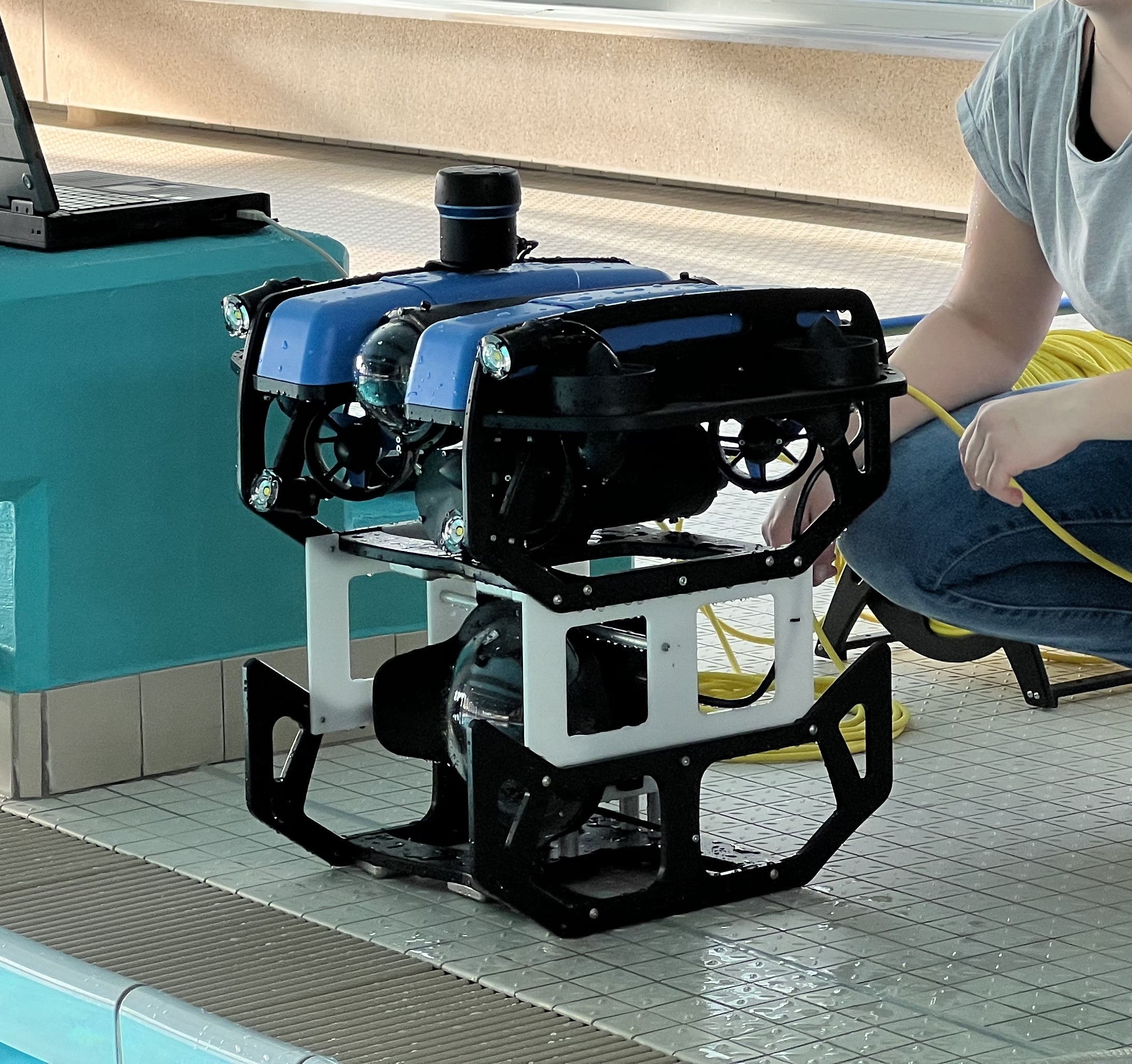
For this project a Sony Alpha 7 II (ILCE-7M2; Sony Europe B.V, 2022) with a lens FE 28 mm F2 (SEL28F20) with a 75° FOV is used. The camera is placed in a Sony A7 II NG V.2 Series UW underwater camera housing kit with a 8″ Dome port from seafrog (seafrogs, 2023). The housing is mounted underneath a BlueROV2, which is an underwater robot with open-source electronics and software (Fig. 1; Blue Robotics Inc, 2022). Because the camera housing is larger than what the payload kit allows, the height was extended by 3D printed plates (Fig. 1, right). The ROV is manually steered on an external computer via the ROV camera stream.

3.2 Calibration frame
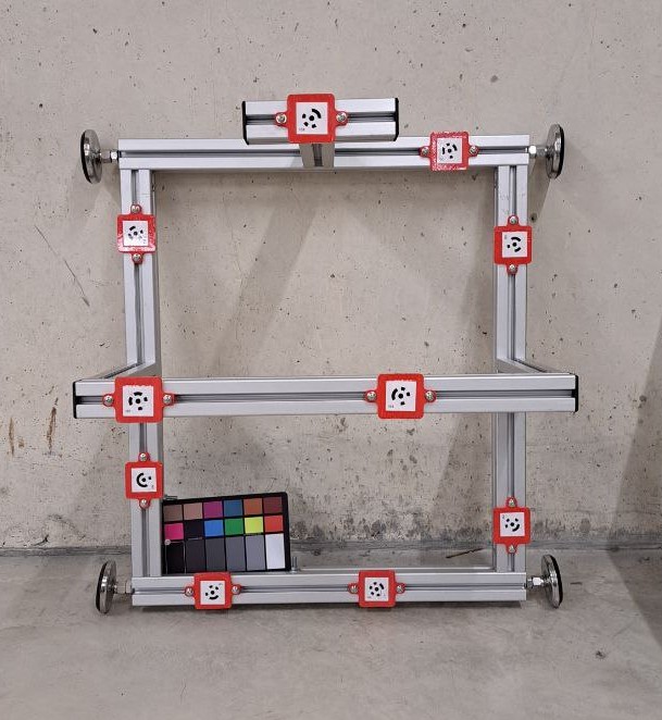
A calibration frame made of aluminium was developed to perform a self-calibration during the 3D reconstruction (Fig. 2). The objects of interest are captured by moving the ROV on an arc on different heights, due to the fixed mounting of the camera, which allows horizontal image capturing only. Multiple exposures should ensure the redundancy of the images.
3.3 Study areas and data acquisition
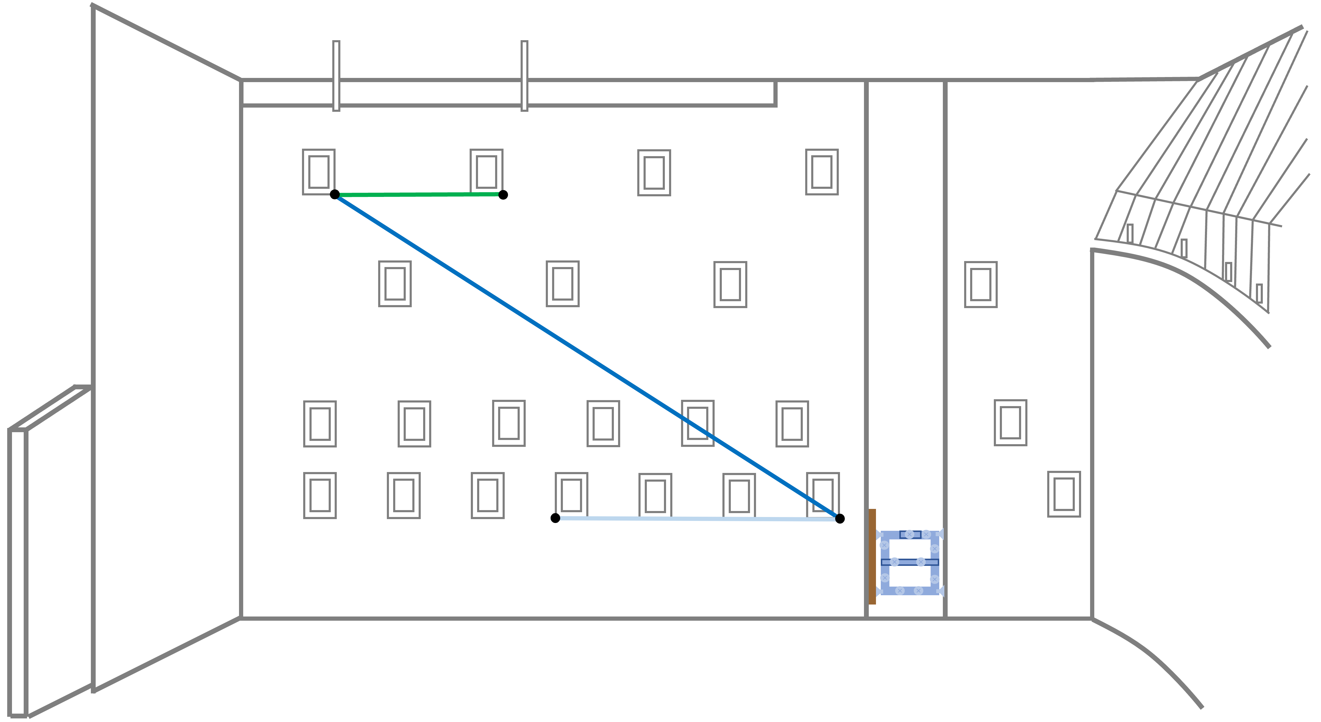
To capture test data three different study areas were evaluated. The indoor swimming pool in Muttenz was used for test capturing in clear water. Furthermore, the water lock was used for the capturing with a reference measurement, which were performed with the laser scanner (Figs. 3 and 4). By filling the lock, different water levels can be set, simulating different depths (1–10 m) of acquisition. And finally, a water filter in the water was used to have a real object (Fig. 3).
The focus of the camera could not be set manually due to the camera trigger software available with the test system. A summary of the image acquisition at the hydropower station in Eglisau can be found in Table 1.
For reference measurements, a Leica RTC360 laser scanner was used to create a dense and very accurate scan of the empty water lock with a 3D point accuracy of approximately 2.8 mm at 20 m and a Leica TS60 total station was used to determine control points for referencing in a local coordinate system with a 3D point accuracy of approximately 2.25 mm at 20 m.


3.4 Camera Calibration
The camera was calibrated in Agisoft Metashape conducting a self- calibration (Agisoft LLC, 2022). The standard frame camera model of Metashape with Brown Distortion Model was used (Brown, 1971).
The parameters focal length (f), principal point offset (x0 and y0), the radial distortion coefficients (K1– K4), the tangential distortion coefficients (P1 and P2) and the affinity and non-orthogonality coefficients (B1 and B2) were determined. Different parameter sets were examined by three methods (Table 2) with original or pre-processed white balanced images. The values are statistically tested using the Student’s t-distribution as in (Harvey & Shortis, 1998).

3.5 3D Reconstruction
For 3D reconstruction, a dense point cloud was computed in Metashape with the self-calibrated cameras. The resulting point cloud of the water lock was compared to the reference scan using the plugin M3C2 in (CloudCompare, 2023). Furthermore, the scale was controlled by three reference lines in the water lock (Fig. 4).
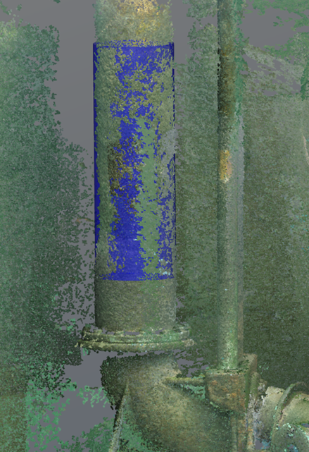
For the point cloud of the water filter no reference data was available. To assess the quality of this mission, a cylinder is fitted into the data using the tool Best Cylinder in Cyclone 3DR from Leica (Leica Geosystems AG, 2023) and the diameter is compared with the nominal value of the manufacturer (32.39 cm).
4 Results
4.1 Camera calibration
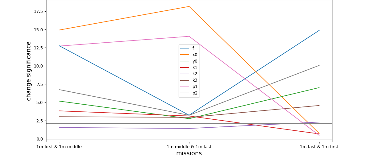
All missions and methods varied significantly, hence, a mission with Method 1 was divided into three parts of 20 images each. For these parts the calibration was recalculated. Fig. 5 shows that even in one mission the camera results in significantly different parameters.
4.2 3D Reconstruction
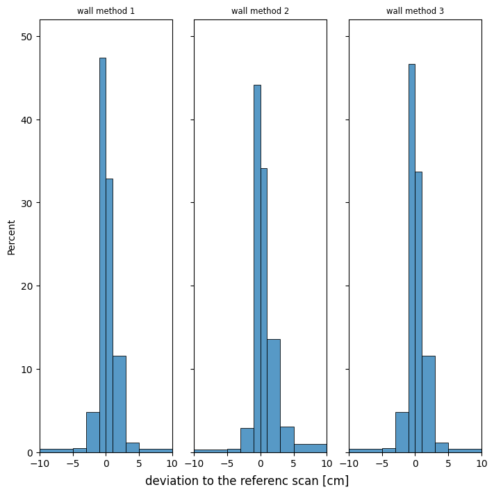
The processed point clouds of the water lock were compared to the reference scan for each calibration method. Fig. 6 shows a close-up of the histograms of the deviation between 3D reconstruction and reference scan. 80 % of the points in the point cloud of Method 1, 78 % of Method 2 and 80 % of Method 3 differ less than 1 cm.
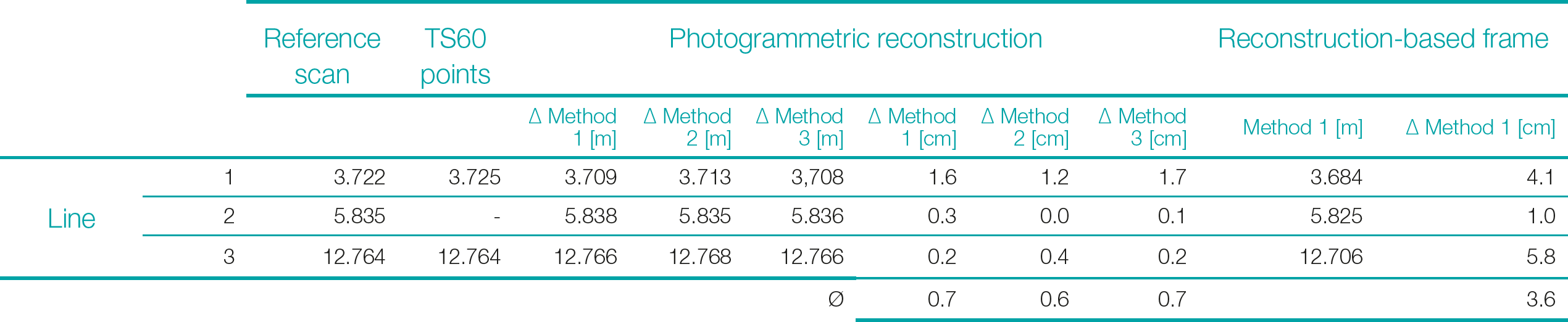
The reference lines show similar results (Table 3). The largest differences occur at the shortest reference distance, which is slightly extrapolating and has less image overlap. One mission (based frame at last column) shows greater differences with an average of 3.6 cm. The mission is orientated based on the calibration frame only and thus the lines were extrapolated.
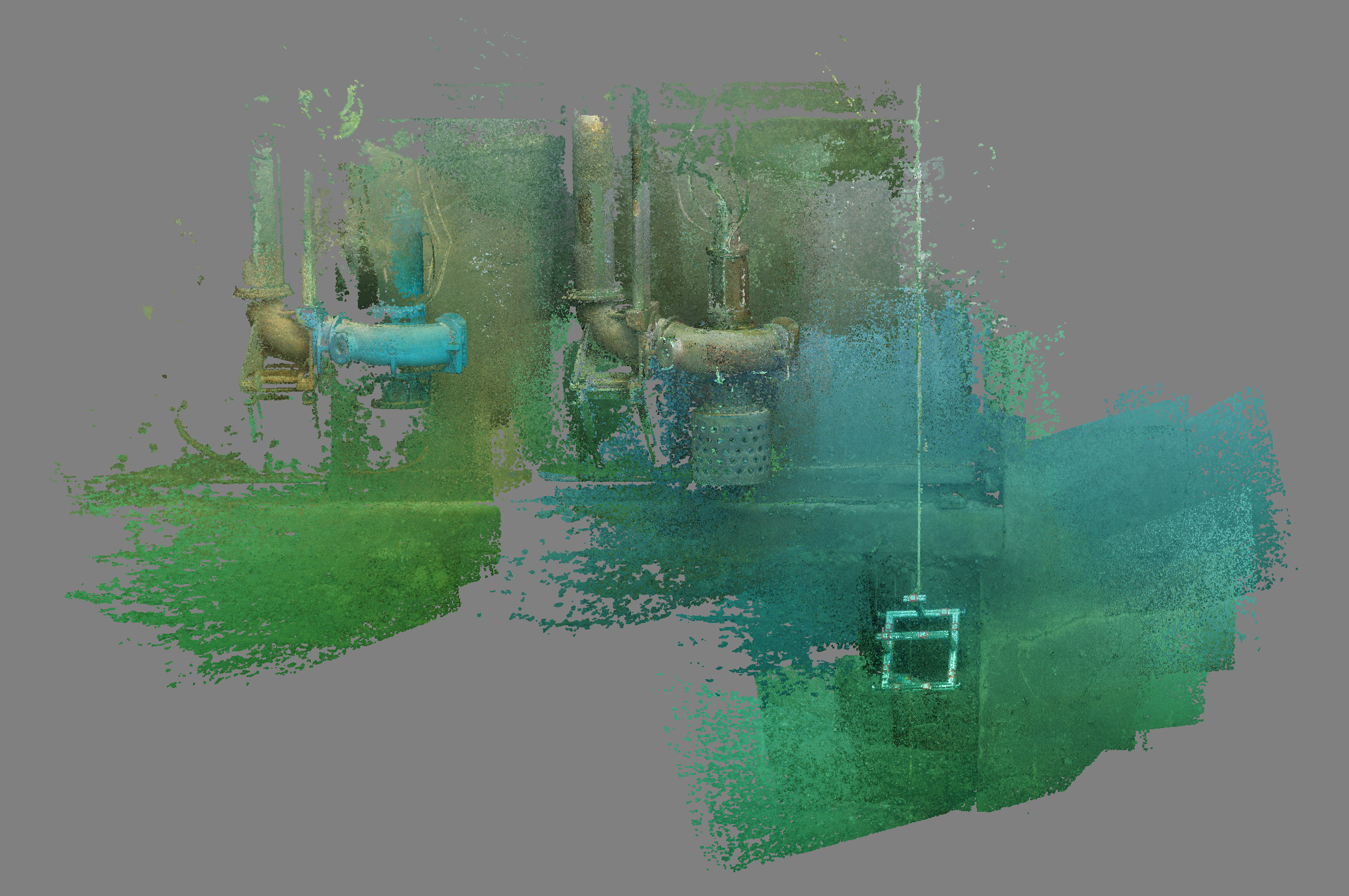
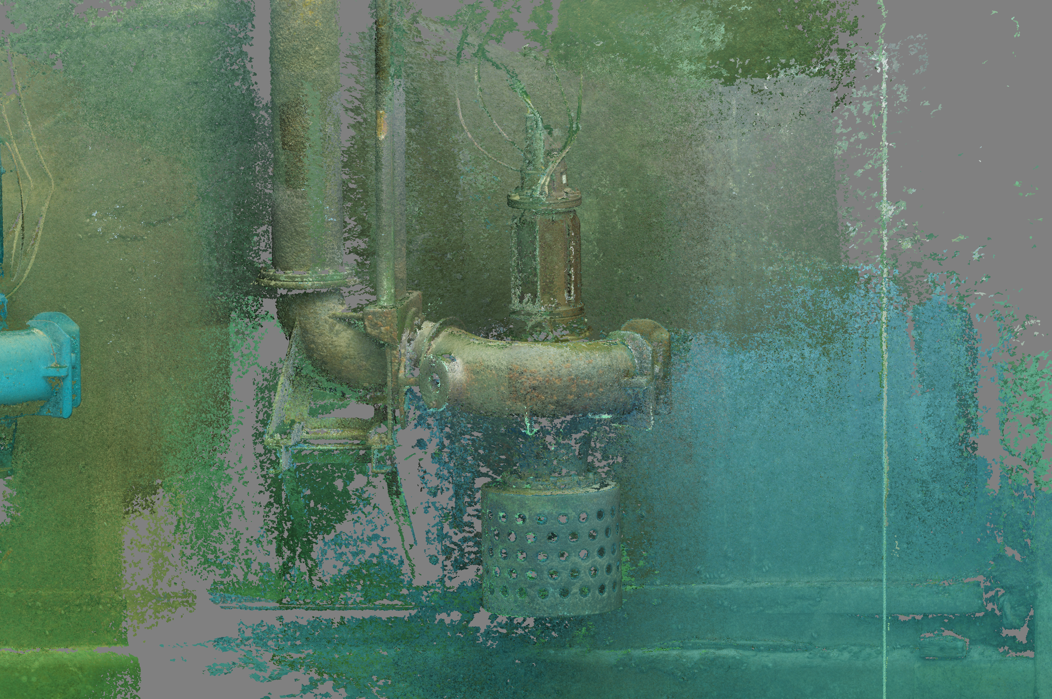
The reconstruction of the water filter (Fig. 5) is referenced based on the calibration frame and results in a very dense point cloud (point distance up to 0.3 mm). However, the reconstructed point cloud has missing parts.
The Best Cylinder tool was applied to the points of the pipe and results in a cylinder with a diameter of 33.12 cm (Fig. 6). Therefore, a difference of 0.73 cm to the nominal diameter resulted.
5 Discussion
The camera calibrations of the different missions, as well as the different calibration methods, show a significant variability (Fig. 3). Possible explanations are the instable mounting in the water housing and the autofocus.
However, as discussed by Luhmann (2018), if the 3D measurements in object space later turns out sufficiently accurate, the corresponding camera calibration is also sufficient. Hence, the processing of the 3D reconstruction can successfully be carried out and investigated.
For each method, a point cloud was reconstructed. There are no major differences between the calibration methods (Fig. 4). Only the point clouds from Method 2 are slightly more widely distributed than those from the other methods. The white balanced images do not improve the results of these missions. Since Method 3 uses more parameters, there are more uncertainties possible. Therefore, it is recommended to use Method 1.
The largest deviations of the distances were found in the extrapolated areas of the water lock, while areas within the control points showed only a deviation of 1 cm. The results from the mission, which orientation is based on the calibration frame, revealed even larger deviations.
The water filter could be reconstructed as a 3D point cloud (Fig. 5). There are certain holes in the point cloud which are probably from a small image overlap, the fixed acquisition angle of the camera or the difficulties with the access of the object. The tool Best Cylinder fits a cylinder in the point cloud. Despite the large extrapolation, as is referenced based on the calibration frame, the difference is 0.73 cm to the nominal diameter.
6 Conclusion and outlook
The photogrammetric reconstruction of underwater objects was successfully implemented with the current set-up. Thanks to the calibration frame and additional control points, true-to-scale and very dense point clouds can be reconstructed, which can be used for further purposes. With well distributed control points, accuracies of sub-centimetres at distances of up to 6 m and 80 % of the points within a deviation of ± 1 cm can be achieved.
While survey areas framed by control points showed less deviation than 1 cm, the largest deviations of the distances were found in the extrapolated areas of the water lock. More calibration frames or scale positioning in the area could potentially reduce the distortion over larger distances. Future research should be in this field.
The calibration results of the different missions and methods show a significant variability. Further investigations with improved camera mounting and better camera control are needed to determine the cause of these variations. A good camera calibration could improve the accuracy of extrapolation.
The water filter was successfully reconstructed as a 3D point cloud, however there are some limitations with this set-up as the point cloud has holes. This can be attributed to low image overlap, the fixed acquisition angle of the camera or the lack of access. The tool Best Cylinder could successfully fit a cylinder into the point cloud, despite the large extrapolation.
References
Agisoft LLC (2022). Agisoft Metashape. https://www.agisoft.com/ (accessed 10 Oct. 2022).
Aragón, E., Munar, S., Rodríguez, J. and Yamafune, K. (2018). Underwater photogrammetric monitoring techniques for mid-depth shipwrecks. Journal of Cultural Heritage, 34, pp. 255–260. https://doi.org/10.1016/j.culher.2017.12.007
BFE (2022). Wasserkraft. https://www.bfe.admin.ch/bfe/de/home/versorgung/erneuerbare-energien/wasserkraft.html (accessed 3 Oct. 2022).
Blue Robotics Inc (2022). BlueROV2. https://bluerobotics.com/store/rov/bluerov2/ (accessed 22 Sept. 2022).
Brown, D. C. (1971). Close-range camera calibration. Photogramm. Eng, 37(8), pp. 855–866.
Bruno, F., Lagudi, A., Gallo, A., Muzzupappa, M., Davidde Petriaggi, B. and Passaro, S. (2015). 3D Documentation of Archaeological Remains in the Underwater Park of Baiae. The International Archives of the Photogrammetry, Remote Sensing and Spatial Information Sciences, XL-5/W5, pp. 41–46. https://doi.org/10.5194/isprsarchives-XL-5-W5-41-2015
Chemisky, B., Menna, F., Nocerino, E. and Drap, P. (2021). Underwater Survey for Oil and Gas Industry: A Review of Close Range Optical Methods. Remote Sensing, 13(14), p. 2789. https://doi.org/10.3390/rs13142789
CloudCompare, 2023. CloudCompare – Open Source project. http://www.cloudcompare.org/ (accessed 1 Feb. 2023).
Harvey, E. S. and Shortis, M. R. (1998). Calibration stability of an underwater stereo-video system: implications for measurement accuracy and precision. Marine Technology Society Journal, 32(2), pp. 3–17.
Leica Geosystems AG, 2023. Leica Cyclone 3DR. https://leica-geosystems.com/products/laser-scanners/software/leica-cyclone/leica-cyclone-3dr (accessed 1 Feb. 2023).
Luhmann, T. (2018). Nahbereichsphotogrammetrie: Grundlagen – Methoden – Beispiele (4th ed.). Wichmann.
McCarthy, J. and Benjamin, J. (2014). Multi-image Photogrammetry for Underwater Archaeological Site Recording: An Accessible, Diver-Based Approach. Journal of Maritime Archaeology, 9(1), pp. 95–114. https://doi.org/10.1007/s11457-014-9127-7
Menna, F., Nocerino, E. and Remondino, F. (2017). Flat vs Hemispherical Dome Ports in Underwater Photogrammetry. The International Archives of the Photogrammetry, Remote Sensing and Spatial Information Sciences, XLII-2/W3, pp. 481–487. https://doi.org/10.5194/isprs-archives-XLII-2-W3-481-2017
Neyer, F., Nocerino, E. and Gruen, A. (2018). Monitoring Coral Growth – Comparing Underwater Photogrammetry and Geodetic Control Network. The International Archives of the Photogrammetry, Remote Sensing and Spatial Information Sciences, XLII–2, pp. 759– 766. https://doi.org/10.5194/isprs-archives-XLII-2-759-2018
seafrogs (2023). Sony A7 II NG V.2 Series UW camera housing kit with 8″ Dome port. https://seafrogs.com.hk/ (accessed 17 Jan. 2023).
Shortis, M. (2019). Camera Calibration Techniques for Accurate Measurement Underwater. In J. K. McCarthy, J. Benjamin, T. Winton and W. van Duivenvoorde (Eds.), 3D Recording and Interpretation for Maritime Archaeology (pp. 11–27). Springer International Publishing. https://doi.org/10.1007/978-3-030-03635-5_2
Sony Europe B.V (2022). Sony Alpha 7 II. https://www.sony.ch/de/electronics/wechselobjektivkameras/ilce-7m2-body-kit (accessed 17 Jan. 2023).
Author’s biography

Between 2012 and 2016, Manuela Ammann learned her surveying skills in an apprenticeship, setting the course for her career. At the FHNW in Muttenz, Switzerland, she immersed herself in geomatics and obtained a Bachelor’s degree from 2016 to 2019. To deepen her knowledge, Manuela completed a Master’s degree in Geoinformation Technology at the FHNW from 2020 to February 2023. During this time, she worked as a research assistant for Stephan Nebiker in the field of photogrammetry. This also opened the door to underwater photogrammetry. Since March 2023, Manuela has continued her academic and professional career as a research associate at the FHNW, working with Pia Bereuter in the field of geoinformation technology.