


Abstract
1. INTRODUCTION AND OBJECTIVE OF THE R&D PROJECT
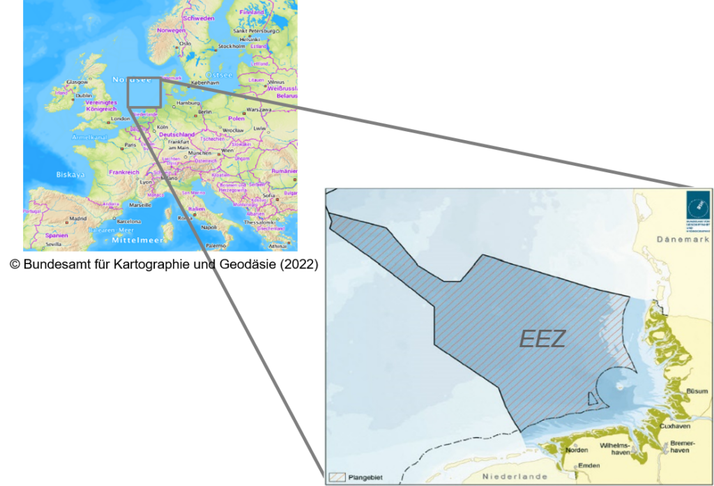
The Federal Maritime and Hydrographic Agency of Germany (BSH) is responsible, among other things, for surveying tasks in German territorial waters and its exclusive economic zone (EEZ) in the North Sea and Baltic Sea. Another area of responsibility includes the spatial planning as well as the assessment and approval of installations for power generation in the North Sea and Baltic Sea. For hydrographic surveying (e.g. close-meshed surveys of fairways and maritime areas), the high-precision real-time positioning service (HEPS) of the national satellite positioning service of Germany, SAPOS (AdV, 2022), has been used since 2009 (Ellmer, 2013) in order to precisely position the survey vessels of BSH in the official coordinate reference system. Since then, this has been successfully achieved in the coastal area of the North Sea, which is optimally covered by SAPOS CORS (Continuously Operating Reference Stations). In contrast, the SAPOS-HEPS service is not available in the offshore area of the EEZ in the North Sea (Figure 1). This therefore results in a fundamental question as to how to achieve reliable, real-time and highly accurate positions, especially in the height component, for offshore hydrographic surveys conducted in in the North Sea.
Two crucial key questions are to be answered in order to accomplish this task:
- How can the height component be accurately and reliably determined in real time?
- How can SSR (State Space Representation) correction data be transmitted to the survey area with high performance?
Initial investigations and test measurements for the determination of highly accurate height components in the offshore area were carried out in 2014 and 2015 by the authors and the basic suitability of the SSR-RTK (State Space Representation-Real Time Kinematic) method was proven (Ellmer, 2013; Jahn et al., 2017). In continuation of this early investigation and test phase, the research and development (R&D) project SSR-RTK correction data service for highly accurate positioning in the German exclusive economic zone in the North Sea was carried out from 2020 to 2022 (Jahn et. al., 2021). This paper presents the results of this R&D project. The core objective was to refine the model and format parameters preliminarily used in 2015 (Geo++, 2020a) of these innovative SSR-RTK technologies based on the experience gained from previous cooperation. The full potential for highly accurate and reliable positioning in the German EEZ of the North Sea is thereby tested in practice using ship time on research vessels.
In this context, BSH has defined the following quality objectives:
- The height accuracy for the position of the antenna in the reference system ETRS89 (European Terrestrial Reference System 1989) must be better than 10cm at 95% level of confidence.
- The convergence time must be less than two minutes upon first initialisation and less than 20s after signal loss according to the accuracy specification stated above.
- The data correction service must ensure a high availability of correction data in the survey area of the German EEZ in the North Sea.
- The format for correction data transmission must be open, licence-free and well document-ted.
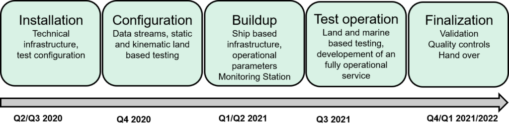
The timeline for the R&D project is shown in the milestone plan in Figure 2. In the first stage, the data connections to the GNSS (Global Navigation Satellite System) CORS were established, the hardware for operating the real-time SSR network in the Cloud was rented and the software components were configured and commissioned. In the further stages, redundancies were established and quality assurance measures were introduced. Test measurements were carried out on land and offshore to investigate and assess the functionality and performance of the prototype.
2. TECHNICAL PRINCIPLES FOR PROTOTYPE DEVELOPMENT
For high-precision real-time positioning of the order of a few centimetres, regularly distributed GNSS CORS are currently used at intervals of 60–100km on average. Together, these form a GNSS reference network (Bauer, 2018). The data from these stations are broadcast with an update rate of 1Hz via networks (e.g. Internet, Virtual Private Network). In the real-time driven adjustment process, the complete GNSS error budget is modelled and distance-dependent terms are described based on highly accurate station coordinates and satellite orbit parameters. For the most part, satellite orbit and clock errors, satellite signal biases, ionospheric and tropospheric propagation delays, carrier phase ambiguities, receiver clock errors and receiver signal biases are determined. The error-corrected distance-independent correction data is parametrised in the Observation Space Representation (OSR) by means of area correction parameter (FKP), Virtual Reference Station (VRS), and Master Auxiliary Concept (MAC) techniques. The correction data are used to generate position solutions at the 1 to 3cm level for the position and height components. These methods are well established, applied in real time and have proven to be robust (Bauer, 2018).
However, the OSR methods reach limits because of the necessary bi-directional communication links between GNSS correction service and rovers, thus limiting the number of possible parallel connections via mobile internet. The required bandwidth for the transmission of correction data also increases with an increase of the number of available satellites. This is because the sum of all distance-dependent error components is always transmitted to the user at a high data rate (Wübbena et al., 2005, 2021). In order to overcome these limitations, Wübbena et al. (2005) introduced the PPP-RTK (Precise Point Positioning-Real Time Kinematic) method. PPP-RTK models systematic errors characterised by different spatial and temporal properties in the state space domain and provides the required corrections for the positioning of a single receiver. The term SSR-RTK network is used to distinguished from an OSR-based calculation processing. With the publication of the State Space Representation Format (SSRZ; Geo++, 2020b), Geo++ GmbH has described a format that optimises the data volumes to be transmitted, enables broadcast-capable communication paths and is suitable for high-precision applications.
The PPP-RTK method is a fundamental conceptual enhancement to the conventional PPP method (Bauer, 2018). The approaches for SSR generation, parametrisation, formatting and achievable accuracy can be different, and there are currently different implementations (e.g. SPARTN, 2022; Hirokawa et. al, 2021). The term PPP-RTK is often understood as a combination of SSR parameters from both global and regional calculations. The method used in this R&D project consistently and completely determines all SSR parameters from the GNSS data of the CORS used and is provided by the GNSMART (GNSS State Monitoring And Representation Technique) software of Geo++ GmbH (Geo++, 2020b).
In order to maintain network availability during the continuous operation of the GNSMART software, a cloud based IT infrastructure was used, characterised by a broadband and non-interruptible internet connection and powerful hardware. Only a high-performance internet connection can guarantee a reliable test and production environment for the delivery of various correction data streams to the user, in which the CORS observations are introduced in real time into the mathematical calculation for the correction data. In addition, remote maintenance must be possible at any time and from any location with internet access for all parties involved to enable short-term interventions during operation and the optimisation of software parameters. An undisturbed operation with a high level of fail-safety must also be guaranteed.
3. DESIGN OF GNSS CORS NETWORK AND SSR-RTK NETWORK CALCULATION
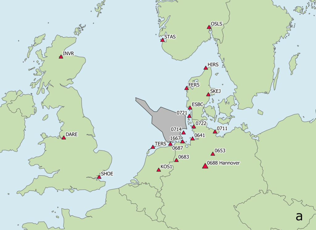
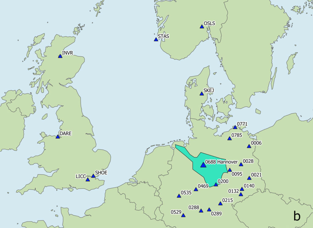
Within the German EEZ of the North Sea, there are no evenly distributed GNSS CORS. A new approach combining irregularly distributed GNSS CORS in a wide- and a narrow-meshed network called North Sea Network (NSN) was therefore implemented. In the dense part of the network along the coast, the average distance within the network (Figure 3a) correspond roughly to the average distance within the German SAPOS network. GNSS CORS in Denmark and the Netherlands supplement the network. GNSS CORS located up to 900km away in Great Britain and southern Norway are included in the wide-meshed part of the network.
Due to the high costs of ship time on research vessels, a second SSR-RTK network called Mainland Network (MLN, Figure 3b) was established on land and put into operation for various test measurements for the entire duration of the project. This second test area roughly corresponds to south-east shifted version of NSN. This allowed for the fictitious replication on land of the Germany EEZ in the North Sea.
Within MLN, one station was set up as a monitoring station in the city of in Hannover and operated permanently for validation tasks. The monitoring station enables various investigations of different receivers and communication tests but primarily serves to monitor the quality of the SSR-RTK network service and the software solution as 24/7/365 coordinate time series (Figures 5 and 7).
Important parameters for the reliable and precise operation of a network are highly accurate CORS coordinates. The process involves an adjustment calculation (Kalman filter) whose initial parameters are estimated together with other model parameters. The coordinates of the GNSS CORS (SAPOS, EUREF1, SDFE2) in the network were available in different datums. At the beginning of the R&D project, these were adjusted in a common coordinate frame (ETRS89/DREF91) and introduced into the further calculations with a small a priori standard deviation (1mm) for all CORS. This coordinate frame is a realization of the official German reference system ETRS89/DREF91.
The GNSMART software determines the state space of individual GNSS error components such as tropospheric propagation delay parameters (state monitoring) from a network of GNSS CORS and provides GNSS correction data in different formats (representation). GNSMART simultaneously processes the undifferentiated GNSS observations of different GNSS signals in a multi-frequency/multi-signal/multi-GNSS adjustment. In addition to station coordinates, the input parameters of GNSMART also include receiver and antenna information, calibrations, and metadata as well as satellite antenna parameters (igs14.atx) and precise satellite orbits (CODE, 2022). The phase ambiguities are resolved from the multi-frequency and multi-signal data of the satellites and the aforementioned input parameters in GNSMART. From these, correction parameters are generated and made available to the user via Ntrip (Networked Transport of RTCM via Internet Protocol) at defined transfer points (SSRZ mount points). With regard to the SSR-RTK networks (Figure 3a and 3b), terms like NSN and MLN are also used here.
In the context of the North Sea project, special adjustments to the configuration of the SSR corrections (e.g. with regard to the interpolation of the atmospheric error budget) were also necessary. On one hand, this was because of the increasing solar activity and the resulting influence on the GNSS data. On the other hand, the heterogeneous network structure of this project (short station distances on the coast; long station distances in the area of the North Sea) requires a separate error modelling.
4. SETUP, OPERATION AND RESULTS OF THE MONITORING STATION
In winter 2020/2021, a monitoring station was set up within MLN (Figure 3b) using a Leica AR25.R4 GNSS antenna with LEIT radome. The antenna is connected to two Septentrio AsteRx SBs via an antenna splitter (Figure 4) and thus allows coordinates to be determined in accordance with a zero baseline. The official coordinates in the ETRS89/DREF91 system serve as reference values as well as a reference for the measurements with the monitoring station. This station simulates a user in a comparable test area to the EEZ with large point distances to neighbouring CORS of up to 190 km and enables a continuous check of the solution status and the performance of the coordinate calculation in MLN by means of reference values.
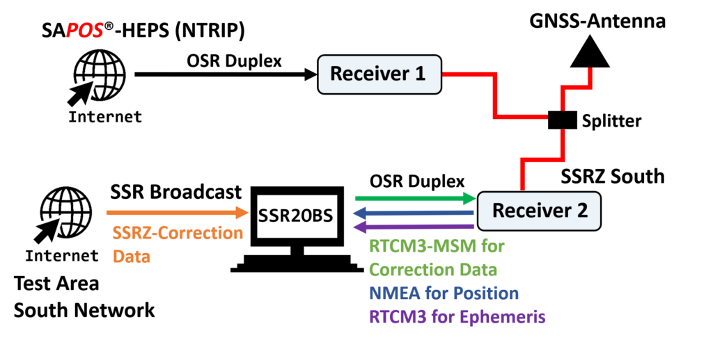
Direct processing of SSR correction data is currently available only in prototype configuration, because commercially available GNSS receivers do not yet have the required interface. A format conversion on a computer was thus necessary. The ssr2obs software for the conversions from state space to observation space was provided by the project partner company Geo++ GmbH. In the concept of a broadcast-capable SSR service, the correction data are processed directly in the GNSS receiver. Ideally, a format in the international RTCM standard must be available for this, which generally is a supported format in the firmware on the rover side (rover engine). The rover would then be able to determine an absolute position of its antenna without direct use of data from a GNSS reference station.
The results from the monitoring station data are thoroughly evaluated when the SSR-RTK solutions from MLN are compared with the conventional correction data of the SAPOS-HEPS service (reference solution in coordinate space).
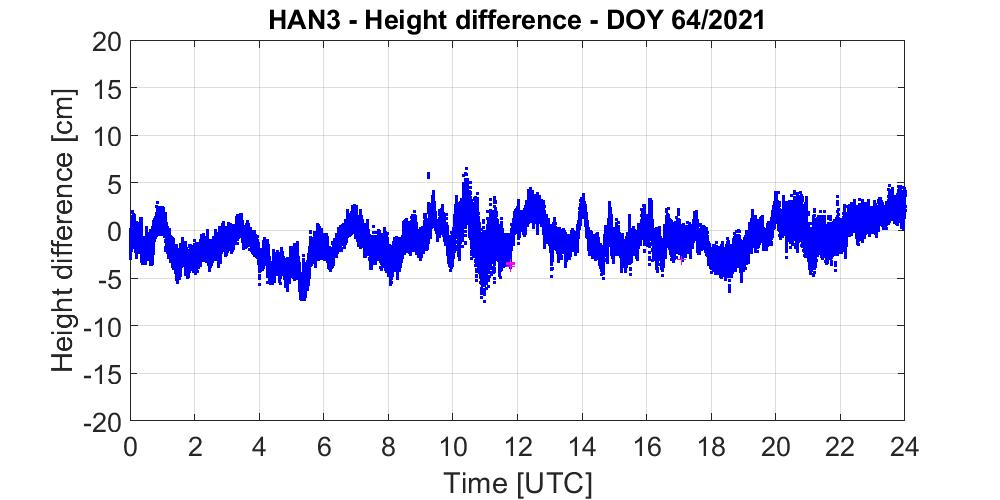
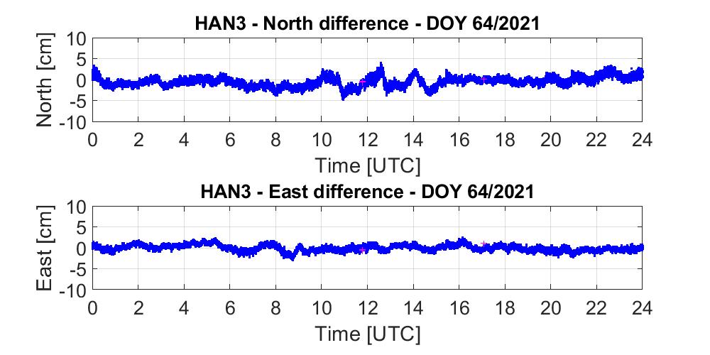
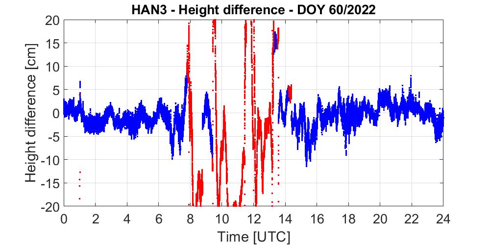
Figure 5 shows an example of coordinate time series for the height and position components of a selected day in 2021 (DOY, day-of-year). Almost without exception, the differences are within the expected range of a few centimetres and confirm the complete modelling of the error budget for this period of investigation. The basic functional status of the monitoring station was obtained through the daily monitoring of the operating status and daily coordinate comparisons with the target coordinates. During continuous operation of the station between 2021 and 2022, stronger deviations in the coordinate comparisons occurred at irregular intervals. The causes of these can primarily be attributed to atmospheric influences.
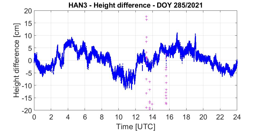
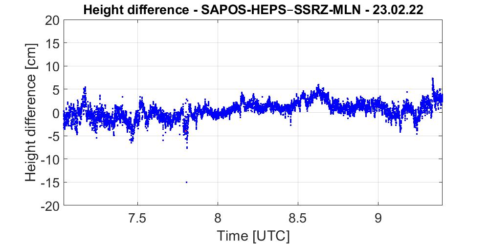
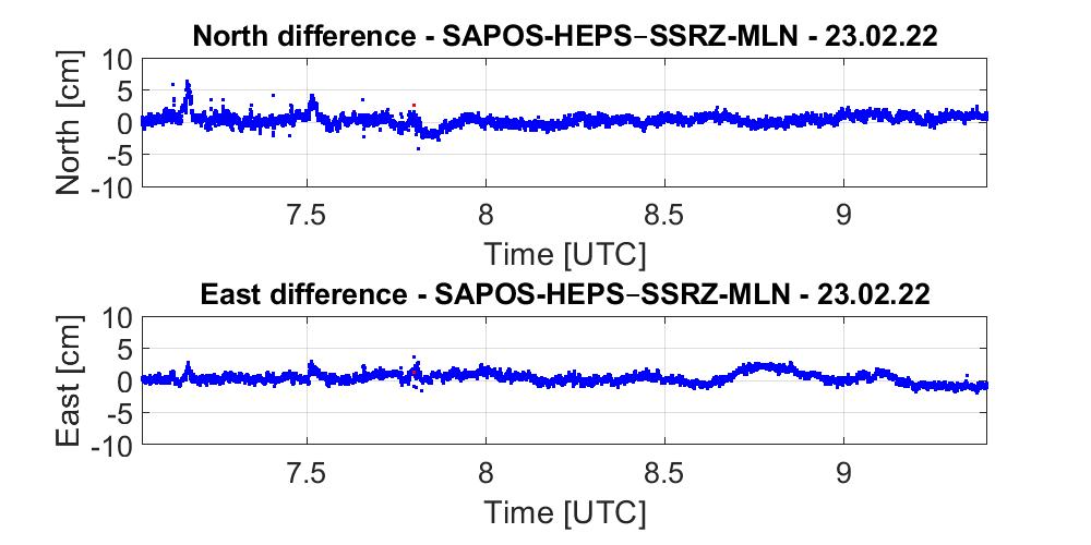
The medium to strong systematic effects of atmospheric disturbances are reflected in the correction data. The coordinate differences in Figure 6a were influenced by areas subjected to heavy rainfalls that occurred frequently on this day, whereas the data underlying the differences in Figure 6b were influenced by strong ionospheric disturbances in the midday hours of the day of investigation. The data come from irregularly distributed CORS with distances of several hundred kilometres in some cases. The conditions for the accurate detection of the GNSS error budget thus differ fundamentally from those in evenly and densely spaced CORS networks.
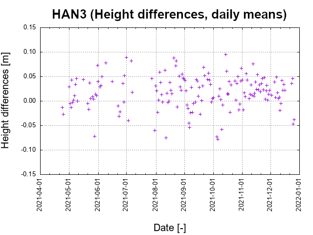
The mean of several quality metrics can be calculated from a statistical evaluation of the Hannover monitoring station data for the year 2021. Figure 7 shows the daily average deviation for the height component. Days with system maintenance, conversions, or model adjustments on the network processing side were omitted. A clear majority of solutions lies within the expected range and attest the accuracy targets for the coordinates set in the project. If we evaluate the RTK status fix for the data series of Figure 7, 72.6% of all solutions are between 90 and 100%, another 14.4% are between 80 and 90%, and 7.5% are between 70 and 80%. This long-term study thus confirms the high quality of the project result.
5. RESULTS OF KINEMATIC TESTS ON LAND
The results presented in Section 4 are from static measurements and confirm the basic functionality of the SSR-RTK prototype. In order to simulate ship borne conditions, a GNSS rover antenna was mounted at the highest point (minimal signal obstruction) of a road vehicle to evaluation the quality under kinematic conditions. A mobile internet connection was setup using an LTE (Long Term Evolution) modem connected to a computer to create a robust communication channel for correction data streams. The GNSS receivers obtained correction data (SSRZ-MLN) via a WLAN (Wireless Local Area Network) hotspot in the vehicle.
Because no reference coordinates are available in kinematic mode, the zero-baseline method was also used here, and the comparisons in coordinate space between the SAPOS-HEPS solution (reference coordinates) and the SSRZ solution were calculated from MLN. The vehicle speed on land (20km/h) was adapted to that of a survey vessel, and a completely wide sky view surveying area was chosen to achieve comparative conditions for real operations at sea.
Figures 8a and 8b show differences of the kinematic coordinate test for the height component and for the position components. The reference solution is based on the dense SAPOS-HEPS network of CORS with the shortest distance of 15km. In the network that forms the basis of the SSR solution (Figure 3b), the distance to the nearest reference station was around 190km. The differences in Figures 8a and 8b surpass the quality objectives of the project: for example, an extremely high GNSS RTK accuracy was achieved for the height component with a standard deviation of 1.8cm, even though the network configuration’s spacing was highly heterogeneous. The receivers for which solutions are shown in Figures 8a and 8b were almost completely (more than 99.9%) in RTK status fix during the test period.
Within the scope of the kinematic tests on land, the convergence time was also verified (Figure 9) ensuring a complete RTK algorithm reset. For this purpose, the cable connection between the antenna and receiver was disconnected for three minutes at fixed intervals during the land survey test, corresponding to a complete signal loss. In contrast, the GNSS receiver, which provided the reference position solutions, was not interrupted.
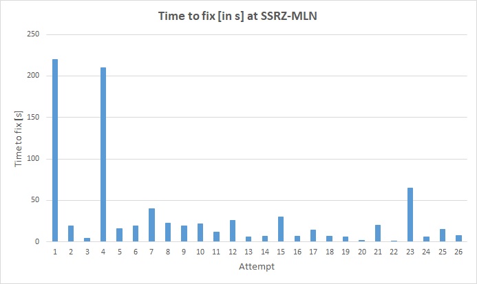
The measured recovery times of the position solutions show the initialisation time necessary until the GNSS receiver reaches kinematic survey mode. The data series in Figure 9 averages 31.7s. Neglecting the two outliers with over 200s (for which no cause could be found), the average value drops to 15.5s, thus confirming the quality objective that initialisation times be achieved within an inhomogeneous network of CORS. Such performances were previously only possible in static applications in networks with short distances between the CORS. During the field tests, despite complete signal interruptions over several minutes, short restart times lasting only a few seconds were possible.
6. ON-BOARD TESTS ON VWFS WEGA
In September and October 2021, two test cruises were carried out with the survey, wreck search and research vessel VWFS WEGA of BSH (Figure 10). The installation of the geodetic receivers and communication systems took place before the first test. It consisted in the general setup of all geodetic components, the basic check of the communication equipment (LTE and VSAT (Very Small Aperture Terminal) systems) and an initial test cruise in the North Sea. In nearshore areas, the GNSS correction data were transmitted by means of LTE, whereas the on-board maritime satellite-based VSAT system was used for offshore areas. In October 2021, the only survey cruise took place in the German EEZ of the North Sea. An extended test scenario was not feasible under the prevailing COVID-19 pandemic. Thus, only one real test cruise in the EEZ was possible in this project.
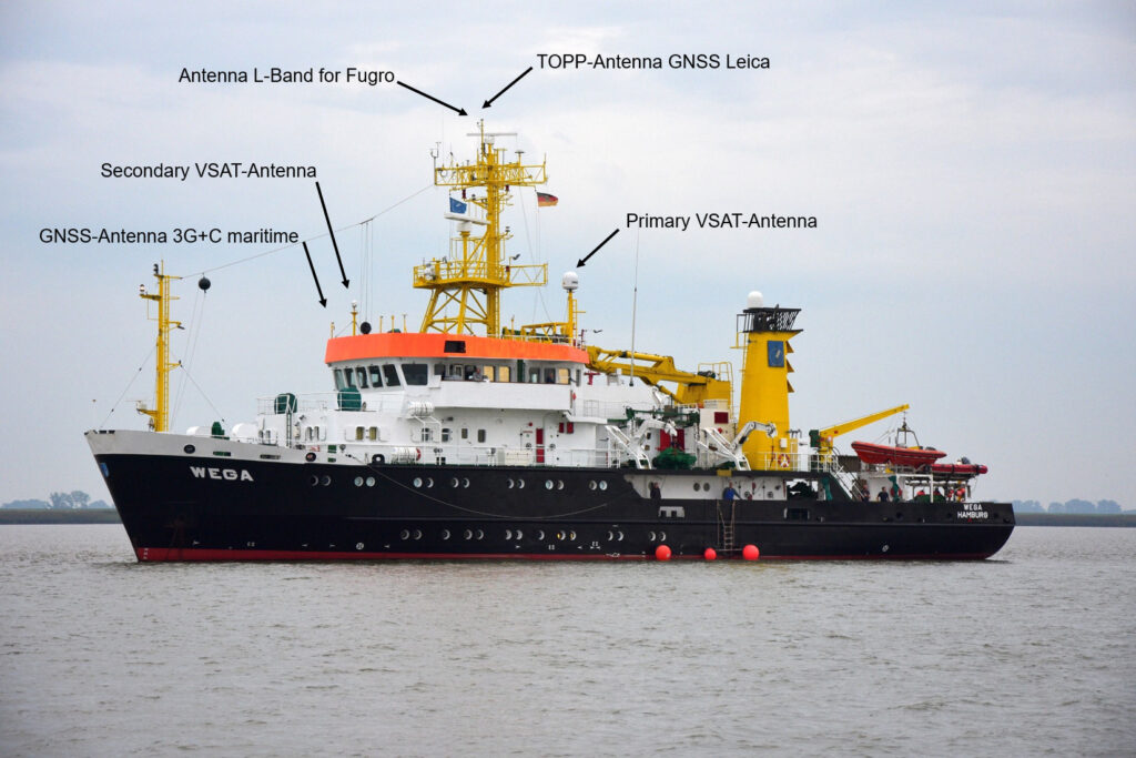
The setup of the GNSS receivers, computers, and communication equipment on VWFS WEGA was completed in accordance to Figures 10 and 11. During the vessel tests, almost identical receivers were used (Septentrio AsteRx SB, AsteRx U). These were identically configured and operated. Only in such manner can the geodetic sensor measurements be compared. All GNSS receivers used in the R&D project were connected via an antenna splitter to a GNSS antenna mounted on the antenna deck of VWFS WEGA. This means that, just like in case of the kinematic tests on land, measurements made during the two test cruises were carried out in zero-baseline mode. The Leica-Topp antenna shown in Figure 11 was used only for a short experiment.
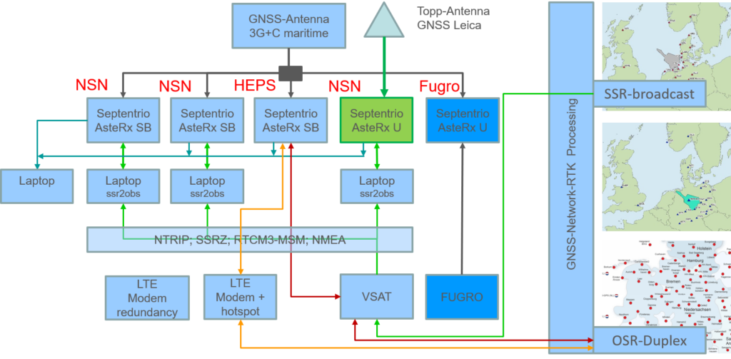
The computers that received the correction data streams from NSN were, just like in case of the kinematic tests on land, equipped with the ssr2obs software to convert the SSR correction data into the receiver-side OSR format. A third computer was used to receive the SAPOS-HEPS correction data, thereby providing a solution comparison for the nearshore area. On VWFS WEGA, the Fugro correction data service (Fugro Marinestar G4+; Fugro, 2022) is currently used as the default positioning service provider. This gave an additional opportunity for comparisons with this provider as well.
7. RESULTS FROM THE ON-BOARD TESTS IN SEPTEMBER AND OCTOBER 2021
The September 2021 investigations served as basic functional tests of the geodetic receivers and the communication equipment. Numerous interruptions of the Internet connections were simulated for both the LTE modems and the VSAT system. The impacts of these on the performance of the data connection re-establishment and the coordinate solution were analysed. The re-initialisation time of the coordinate solution was also of interest. In all tests, after the connections were restored, the times were measured until the RTK fixed solution was obtained. In all cases, the re-initialisation times remained below 30s. Only when the receiver power supply was interrupted (cold start tests), was the re-initialisation time well in excess of 30s.
7.1 Availability of GNSS correction data in the German EEZ of the North Sea
Figure 12 provides an overview of the supply of correction data to VWFS WEGA during the entire October 2021 survey cruise. The proportions of the RTK statuses fix (green), float (yellow), and stand-alone (red) are displayed as pie charts. The data were collected from the GNSS antenna on the antenna deck and the correction data were provided via the VSAT system from NSN. Table 1 shows the corresponding numerical values for Figure 12.
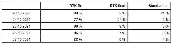
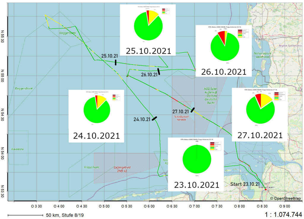
The test cruise achieved a high-quality standard with an average of 87.4% of RTK fixed solutions during the entire cruise duration. On October 24th 2021, the outermost tip of the German EEZ in the North Sea was navigated. The lower percentage of RTK fixed solution can be explained by the fact that a processing parameter was set too low for the interpolation of ionospheric and tropospheric corrections in the ssr2obs software. Due to large distances, the interpolation used not enough correction data available from the GNSS CORS. After matching the parameters in the software with the available station distances, the receiver was able to resolve the ambiguities and a RTK fixed solution was achieved. Table 1 clearly shows that the basic supply of correction data in the German EEZ of the North Sea was high during this test cruise. In well over 90% of cases, internet connectivity was maintained via the on-board VSAT system.
7.2 Investigations of data communication
During both the September and October 2021 test cruises, the reception performance of the VSAT system installed on board VWFS WEGA were investigated. During various turn manoeuvres, the impacts of heading changes on the reception of NSN correction data via the VSAT system were detected. At a north azimuth of 140° (approx. ±5°), the communication links were sometimes completely severed. It was shown that the switching between the primary and secondary antenna did not occur without interference (Figure 10). Based on the findings of this test cruise, the configuration of the satellite communication system was adjusted so that error-free operation is now ensured.
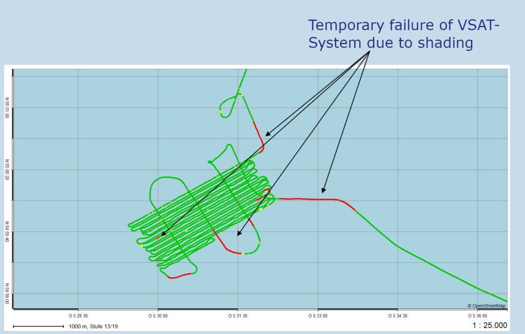
On October 26th 2021, VWFS WEGA’s multibeam echo sounder was operated for several hours. The multibeam survey line planning was designed in such a way that the impacts of the aforementioned communication disturbances were minimised. The surveyed track lines and RTK status are both illustrated in Figure 13 and show that well over 90% of all solutions were in the RTK fixed status. Throughout the survey, the GNSS receivers operated with the different correction data streams.
7.3 Investigations on shadowing and signal interference by vessel superstructures
While moored at port, the impacts of antenna mast shading on GNSS signal reception were investigated. A GNSS antenna was mounted in such a way that the sky view was partially obstructed by the mast, and the data of all GNSS receivers were recorded. In Figure 14, a photo taken with a fisheye lens from the GNSS antenna perspective shows the antenna mast of VWFS WEGA and the secondary antenna of the VSAT system (in the same orientation as Figure 15). Based on this technical setup, the carrier-to-noise ratio (C/N0) of the signals of the L1 frequency was evaluated on four days, and the shadowing and signal interference were analysed. The deviations from a reference C/N0 model were limited to ±6dB-Hz; these were displayed as a sky plot and centred and oriented on the location of the GNSS antenna.
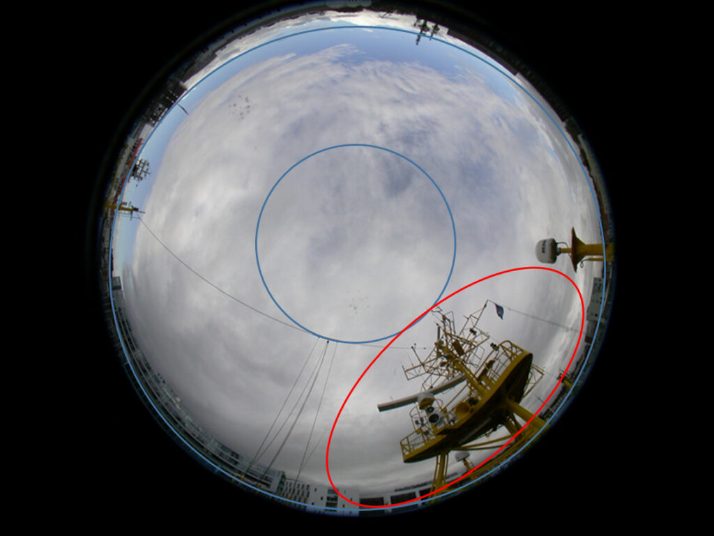
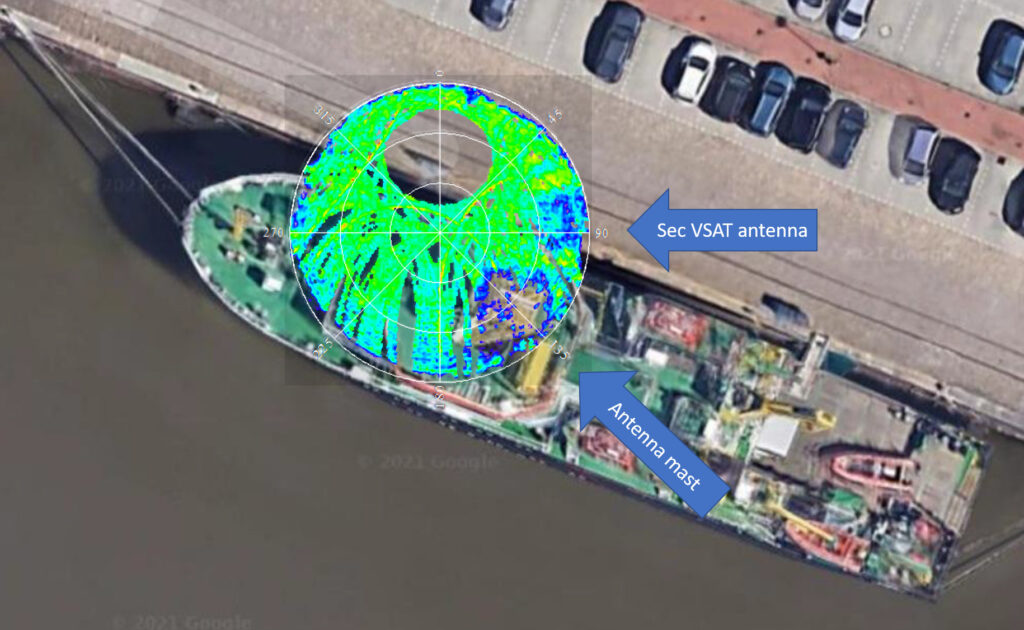
Figure 15 is a sky plot of color-coded C/N0 deviation values along the satellite trajectories. It can clearly be seen that at an average azimuth of 135°, strong shadowing and degradation of signal quality occurs because of the antenna mast. The secondary VSAT antenna is also shown in the sky plot at a mean azimuth of 90°.The signal degradations caused by the antenna mast extend to almost 60° elevation and those caused by the secondary VSAT antenna to just under 30° elevation. The results of these investigations show that the GNSS signals obstructed by the mast are already so strongly degraded that they should be discarded altogether. In addition to shadowing, there is a high risk of signal diffraction, which can cause systematic errors in precise applications and thus lead to an almost complete loss of high-quality signals in those areas. The installation of GNSS antennas at interference-free or at least low-interference sites on a vessel should therefore always be favoured.
8. RESULTS IN COORDINATE SPACE
A key objective of this R&D project was to develop a GNSS-based real-time method for providing highly accurate height coordinates in the Germany EEZ of the North Sea. In Table 1, it was shown that the RTK fixed status was achieved to just under 90% of the time. It is more difficult to derive a robust reference for the comparison of height coordinates from NSN. In this project, the following correction data services were used to generate comparative values:
- SAPOS-HEPS in the nearshore area within the area covered by CORS
- SAPOS-HEPS outside the area covered by CORS (correction data are extrapolated)
- Fugro Marinestar 4G+
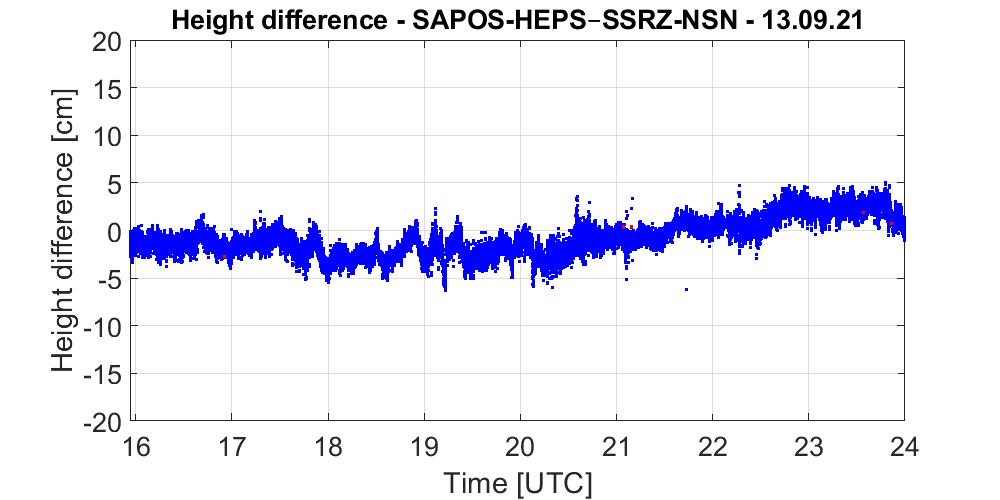
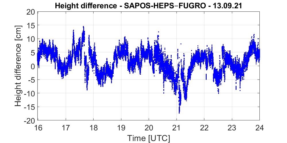
In September 2021, comparisons were first made in the nearshore area. Using GNSS correction data from NSN, height coordinates of VWFS WEGA (GNSS antenna 3G+C maritime, Figure 10) were determined at a distance of 120km from the nearest reference station and compared with height coordinates from the SAPOS-HEPS (Figure 16a) and Fugro Marinestar 4G+ (Figure 16b) services. While NSN and SAPOS-HEPS differences were within expected values (RMS of about 2–3cm, maximum amplitudes of 5cm), the SAPSO-HEPS and Fugro differences were much more scattered with amplitudes between ±15cm. Solutions from the Fugro service therefore do not achieve the quality required to be used as reference.
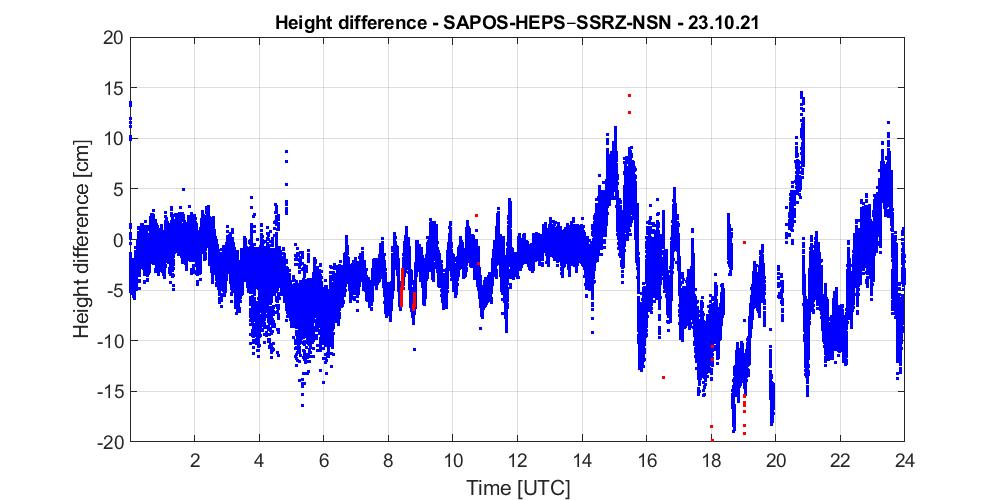
The SSR correction data from NSN are computed using the GNSMART software. In addition to the correction data, extensive quality information is provided, which can be used to assess the operating performance. Figure 17 shows a 24-hour representation of the GNSS satellite ambiguity resolutions in the GNSMART computation process on September 15th 2021. The coloured circles mark the areas where the ambiguities of many satellites were resolved. The markings correspond to those in Figure 18, which show coordinate comparisons between the solutions from NSN and from the SAPOS-HEPS service. On the one hand, there is a high correlation between the number of fixed satellites (Figure 17) on network side and the small coordinate differences between SAPOS-HEPS and NSN. On the other hand, there is a weak correlation between the changes in the fixing behaviour of the ambiguities on the network side and the periodic behaviour of the coordinate differences. This suggests non-modelled residual errors, the causes of which include:
- atmospheric influences and consequential short-term changes in the ionosphere and tropo-sphere, especially in the North Sea;
- an inadequate station design that can lead to multipath effects;
- missing or inadequate antenna calibrations at international stations.
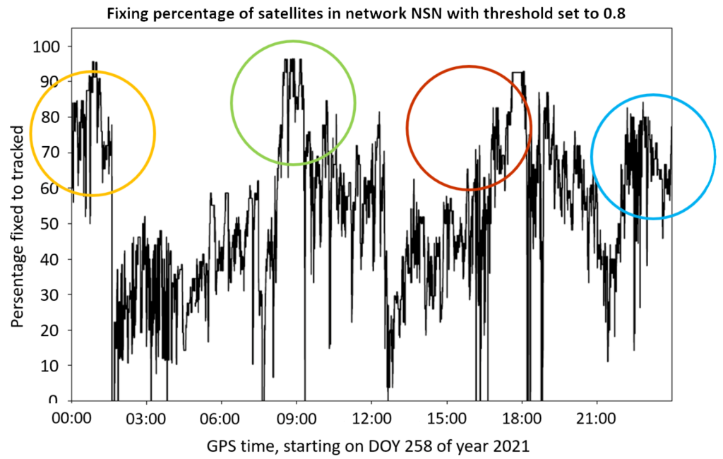
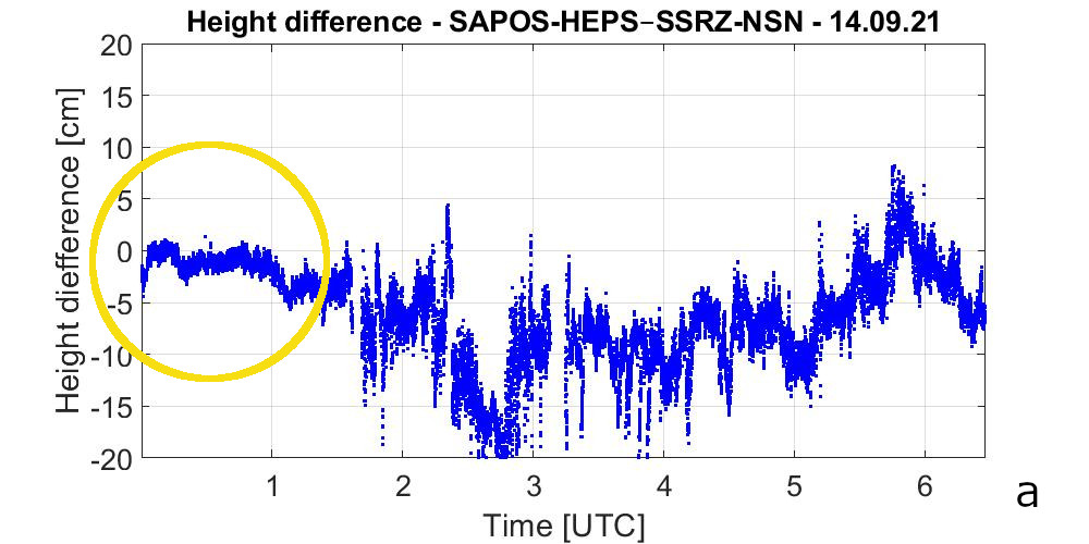
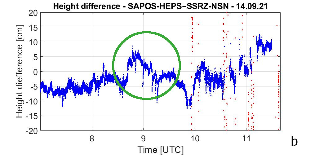
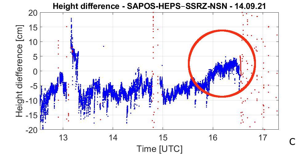
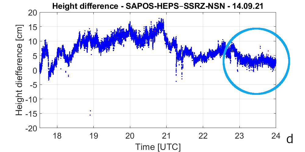
Figure 18. Coordinate comparison on September 15th 2021 between SAPOS-HEPS and NSN with the RTK fixed solution (blue data points) and the RTK float solution (red data points).
The failures in the coordinate comparisons (RTK float solution, red) visible in Figures 18b and 18c are caused by turn manoeuvres of VWFS WEGA, which were carried out to investigate the on-board communication systems.
The reference solution used in the R&D project is based on the correction data of the SAPOS-HEPS service. This service provides reliable correction data for areas that are enclosed within the network of CORS. Outside this coverage, correction data can only be predicted and decreases in quality with increasing distance from the margins of the network. The German EEZ of the North Sea is clearly outside the area of the SAPOS-HEPS service. Thus, during the October 2021 test cruise, a comparison with a reliable reference dataset was only possible on the first survey day, October 23rd 2021 between 12:00AM and 5:00PM UTC. Moreover, the comparison was limited to measurements made within 60km from shore. This comparison is shown in Figure 19b. The cruise started at around 12:00PM UTC and after having travelled parallel to the coastline, the vessel left the SAPOS-HEPS coverage area at around 5:00PM UTC. Good results were obtained between 12:00AM and 3:00PM UTC, but deteriorated afterwards. This was caused by continuous failures in the data from the distant CORS in England and Norway (from about 3:00PM UTC, Figure 19b). These failures led to a continuous decrease in fixed ambiguities in the network solution. The number of SSR correction parameters used to resolve the position of the GNSS antenna on VWFS WEGA thus varied to some extent. The stability of the network was particularly high during the entire measurement day (almost 100%; cf. fixing rate, Figure 19a). This applies to both networks, SAPOS-HEPS and NSN.
9. OUTLOOK
This two-year research and development project demonstrated the potential of the new innovative SSR-RTK technology to achieve highly accurate and reliable positioning in the Germany EEZ of the North Sea. However, further work is required to operate a future real-time correction data service. Because of the heterogeneous network structure, the availability, data quality, and number of CORS must be increased to optimise the reliability of the data streams when calculating the error models. Because of the high dynamics of the model parameters for the test area, systematic influences from atmospheric disturbances of the ionosphere and troposphere should be analysed in more detail to improve the model calculations accounting for the large station distances. Additional stations on platforms in the North Sea could be beneficial for supporting SSR model calculations and generating SSR correction data. Technical and quality assurance measures are essential for long-term operation. Robust communication for transmitting SSR corrections is a key issue, and a permanently operated monitoring station for monitoring the operating status is indispensable.
10. ACKNOWLEDGMENTS
This R&D project contains data from The Danish Agency for Data Supply and Efficiency (SDFE). Stations of use: ESBC, FER5, HIRS, SKEJ and stations from the EUREF Permanent Network (Bruyninx et al 2019).
11. REFERENCES
AdV (2022). SAPOS – the German satellite positioning service, www.adv-online.de/Products/SAPOS/, viewed August 2022.
Bauer, M. (2018). Vermessung und Ortung mit Satelliten – Globales Navigationssatellitensystem (GNSS) und andere satellitengestützte Navigationssysteme. 7th, Wichmann, ISBN 978-3-87907-634-5.
Bruyninx, C., Legrand, J., Fabian, A. and Pottiaux E. (2019): GNSS metadata and data validation in the EUREF Permanent Network, GPS Solut (2019) 23: 106. https://doi.org/10.1007/s10291-019-0880-9 .
CODE (2022). Centre for Orbit Determination in Europe – Analysis Centre – Astronomical Institute, https://www.aiub.unibe.ch, viewed August 2022.
Ellmer, W. (2013). RTK in Referenznetzen auf See – Fokus Kommunikation. In: DVW e.V. (Eds.): GNSS 2013 – Schneller. Genauer. Effizienter. DVW-Schriftenreihe, Volume 70, pp. 181–188.
Fugro (2022). https://www.fugro.com/, viewed August 2022.
Geo++ (2020a). Geo++ State Space Representation Format (SSRZ). Version 1.0, 21 September 2020, Geo++ GmbH, Garbsen. www.geopp.de/ssrz/, viewed August 2022.
Geo++ (2020b). www.geopp.de/gnsmart, viewed August 2022.
Hirokawa, R., Fernández-Hernández, I. and Reynolds, S. (2021). PPP/PPP-RTK open formats: Overview, comparison, and proposal for an interoperable message. NAVIGATION: Journal of the Institute of Navigation December 2021, 68 (4), pp. 759–778. DOI https://doi.org/10.1002/navi.452.
Jahn, C.-H., Riecken, J., Trautvetter, C., Freitag, M., Kurtenbach, E., Fabian, G., Dick, H.-G. (2017). Quo vadis SAPOSR? – Zukünftige Entwicklungen des Positionierungsdienstes der Landesvermessung. In: DVW e. V. (Hrsg.): GNSS 2017 – Kompetenz für die Zukunft. DVW-Schriftenreihe, Band 87, 133–150.
Jahn, C.-H., Schumann, R., Vahrenkamp, B., Westfeld, P., Wübbena, G., Schmitz, M. and Wallat, C. (2021). SSR-RTK–Korrekturdatendienst für hochgenaue Positionierung in der deutschen ausschließlichen Wirtschaftszone in der Nordsee: Nordsee-Vernetzung. ZfV –Zeitschrift für Geodäsie, Geoinformation und Landmanagement, zfv 2/2021, pp. 126–130. DOI 10.12902/zfv-0342-2021.
SPARTN (2022). Secure Position Augmentation for Real-Time Navigation, https://www.spartnformat.org/, viewed August 2022.
Wübbena, G., Schmitz, M. and Bagge, A. (2005). PPP-RTK: Precise Point Positioning Using State-Space Representation in RTK Networks. 18th International Technical Meeting, ION GNSS-05, September 13-16, 2005, Long Beach, California. www.geopp.com/pdf/ion2005_fw.pdf.
Wübbena, G., Wübbena, J., Wübbena, T. and Schmitz, M. (2021). SSR und zukünftige GNSS-Anwendungen. Präsentation BfG Kolloquium “Big, Smart, Geo Data – Veränderungen in der Geodäsie zum Nutzen der Wasserstraßen”, 23–24 November 2021.
12. AUTHORS BIOGRAPHIES
Dr.-Ing. Cord-Hinrich Jahn graduated as a geodesist in 1986 from the University of Hannover (Germany). In 1992, he earned his PhD on the use of GPS to detect recent crustal movements on Iceland. He then worked on several R&D projects to develop and commission the Satellite Positioning Service (SAPOS) in Germany. Between 2007 and 2016 he was head of the working group spatial reference of Germany. In his current position as head of the spatial reference department in Lower Saxony, he is responsible for the development of the spatial reference and the operation of the SAPOS service in Lower Saxony and the SAPOS central office in Germany. Email: cord-hinrich.jahn@lgln.niedersachsen.de
Dr.-Ing. Patrick Westfeld graduated as a geodesist in 2005 from TU Dresden (Germany). He conducted research in the fields of photogrammetry and laser scanning and completed his PhD in 2012 on geometric-stochastic modeling and motion analysis. Since 2017, Dr. Westfeld heads R&D at BSH, the German Federal Maritime and Hydrographic Agency. The activities of his section range from conceptual issues pertaining to hydroacoustic and imaging sensor technologies, sensor integration and modeling, algorithmic development up to application-specific implementation and practical transfer in the production environment. Email: patrick.westfeld@bsh.de
Bernd Vahrenkamp studied geodesy at the University of Hannover (Germany). This was followed by his legal clerkship. In 1995, he took over the management of the surveying and hydrography service for the expansion of the Main River in the Federal Waterways and Shipping Administration. Since 2000, he has been responsible for the marine surveying service on the German North Sea at the Federal Maritime and Hydrographic Agency. Email: bernd.vahrenkamp@bsh.de
Dr.-Ing. Gerhard Wübbena received his PhD in geodesy from the University of Hannover, (Germany). He works in the field of GNSS since 1983. In 1990, he founded the company Geo++ GmbH, which develops satellite navigation and positioning software and systems. Among these are post-processing systems and the real-time system GNSMART. He is an active member of international working groups of the IGS and RTCM. A focus of his work is the development and application of SSR technology and its standardization. Email: gerhard.wuebbena@geopp.de
Dr.-Ing. Martin Schmitz received his PhD in geodesy from the University of Hannover (Germany). He has been working in the field of GNSS since 1991 and is involved in research and development of precise GNSS positioning with a focus on RTK networks and SSR technology, antenna and station calibration. He is a member of working groups of the IGS and RTCM. Email: martin.schmitz@geopp.de
Robert Schumann studied Geodesy and Geoinformatics (2012–2018) at University of Hannover (Germany) after attaining the entrance qualification. From 2019 to 2022, he worked at the spatial reference department in Lower Saxony and was involved in the development of a real-time high-precision positioning SSR-RTK service for the German EEZ of the North Sea. Since 2022, he works for Federal Waterways and Shipping Administration.
Christoph Wallat received his degrees in geodesy from the University of Hannover (Germany). He has been working in the field of GNSS since 2014. From 2019 to 2021, he worked as a support engineer at Geo++ GmbH where he was involved in several projects. Since 2022, he works for Leica Geosystems GmbH Vertrieb.