
Preamble
This manuscript is a reprint of the original paper previously published in 1961 in The International Hydrographic Review (IHR, https://ihr.iho.int/): Tucker, M. J. (1961). Beam identification in multiple-beam echo sounders. The International Hydrographic Review, 38(2), 25–32. https://journals.lib.unb.ca/index.php/ihr/article/view/26493
Precis
When using a multiple-beam echo sounder there is some difficulty in distinguishing port and starboard beams, and occasionally even between the first and second beams on one side. By using a transducer with the axial beam stronger than the rest, and tilting the transducer so that this beam points to one side, the corresponding port and starboard beams may be distinguished by their different intensities.
1 Introduction
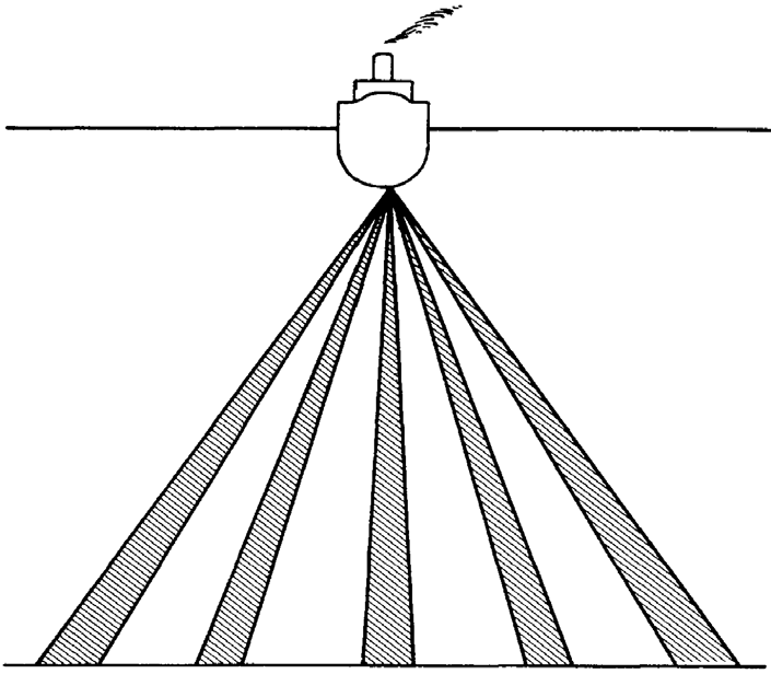
When examining the sea floor using echo rangers, the information obtained may be considerably increased by using a transducer with several secondary beams, or side-lobes (Chesterman et al., 1958). The application of multiple side-lobes to echo sounding, that is, for determining the bathymetry of the sea floor, has been discussed by Tucker (1960) and by Howson and Dunn (in press). In this application, the transducer is arranged to have a series of beams pointing sideways from the ship as well as vertically (Fig. 1). The echoes from these beams are all received by the same receiver, but will usually have different ranges and can therefore be distinguished on the recording chart, particularly if the beams are narrow compared with the angle between them, which can be achieved by designing special transducers, or by using the multiplicative system described by Howson and Dunn (ibid.). However, with this type of beam pattern there is no means of distinguishing port and starboard beams, and in the simpler systems the beams are comparatively wide and their echo patterns tend to get confused.
On a recent cruise of the Royal Research Ship Discovery II, it occurred to the author that a more easily interpretable pattern could be obtained if the transducer were tilted so that the axial beam of the transducer, which is the strongest, points to one side. Port and starboard beams at similar angles to the vertical now differ in intensity and can be distinguished. Moreover, where the traces from them are superimposed on the recorder chart, the stronger one can be followed and so at least some information is obtained. In practice, using the simple additive system, the echo patterns from the side with the stronger beams usually obscure the pattern from the other side, so that information is only obtained about the sea bed to one side of the ship, except when the bed slopes very steeply.
2 Records
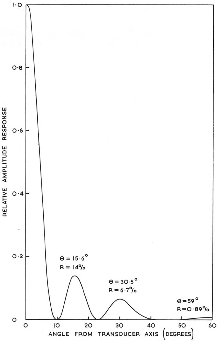
The special sonar installed in R.R.S. Discovery II for fishery and geological research (Tucker & Stubbs, in press) can be pointed vertically downwards and used as an echo sounder. For the records shown here it was tilted slightly off vertical to the starboard by the angles stated in the figure captions. The beam pattern of the transducer in the athwartship’s plane is shown in Fig. 2. The fore-and-aft beam width was 1.3°, the frequency approximately 36 Kc/s, and the pulse length about 2 m/s. The transducer could be stabilized against roll, but some records were taken with it unstabilized in order to examine the effect. Some typical records are shown in Fig. 3, 5 and 6. Unfortunately it was not possible to obtain many records on this occasion because the equipment was mainly in use for survey work. However, these records give some idea of the type of result that can be obtained.
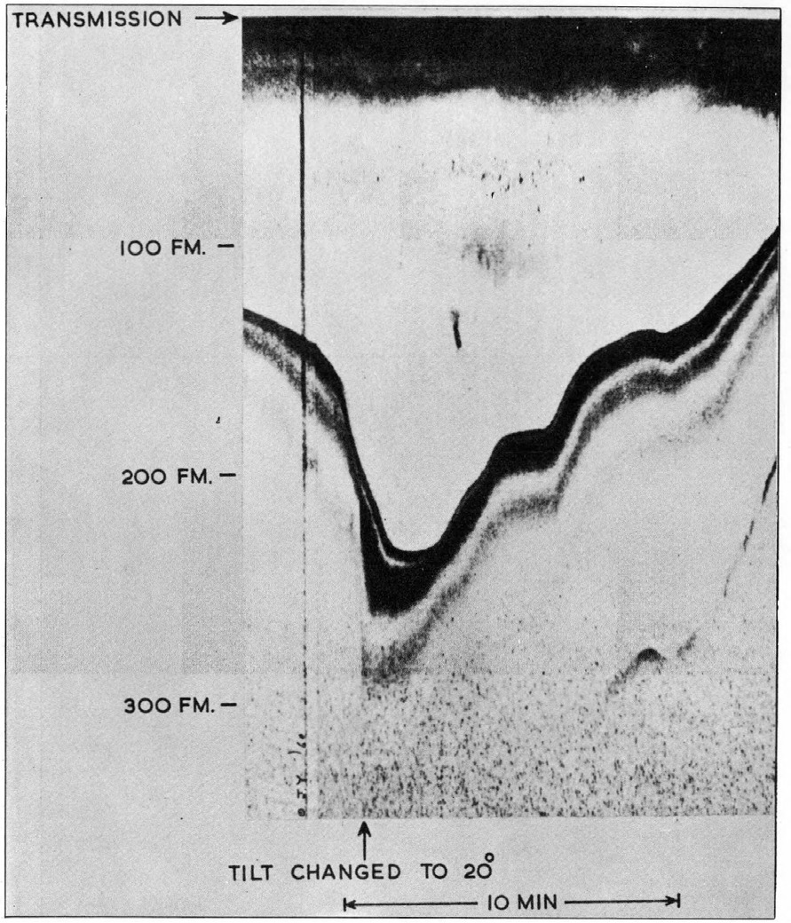
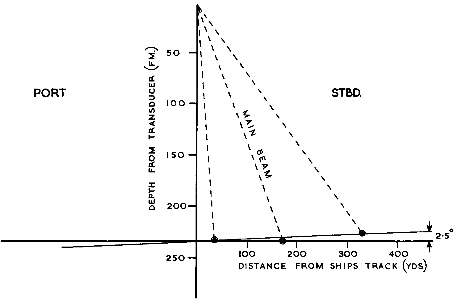
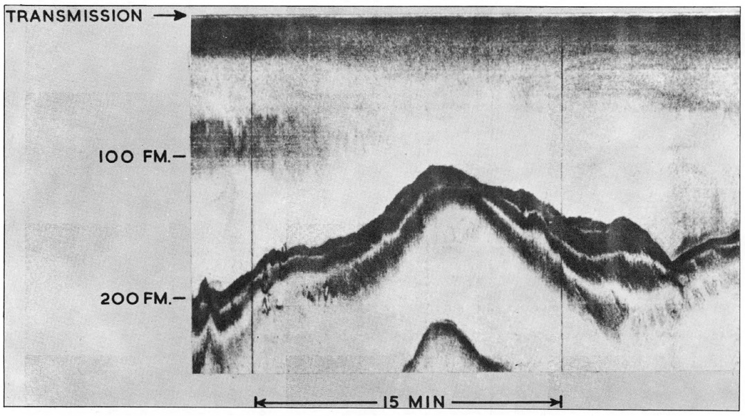
The record shown in Fig. 3 was taken approximately 30 miles ESE of Cape St. Vincent on a course of 290° (T), and shows a submarine canyon. Fig. 4 shows the corresponding geometrical construction using the deepest sounding in each track. This shows that the bed of the canyon was sloping downwards at an angle of about 2.5° away from the coast. The transducer was stabilized using a gyroscope as reference, and taking errors of measurement into account, the angle should be accurate to about ± 1.5°. It will be seen that the outside lobe crossed the bed of the canyon before that directly under the ship. The time difference was approximately 25 sec and the ship’s speed approximately 9 knots. This allows calculation of the angle of the canyon bed relative to the ship’s track, and gives a figure of 110°.
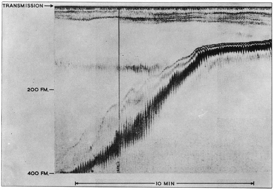
For comparison, Fig. 5 shows a record with the transducer axis vertical. Though this gives quite a graphic picture of the nature of the sea bed, it is more difficult to interpret quantitatively.
Fig. 6 shows a record with the transducer unstabilized. The weather was calm and the ship was rolling only ±5° approximately (max. roll). The beam pattern is still reasonably clear, but could obviously get confused if the rolling were much worse.
3 Discussion
It has been demonstrated that considerable extra information can be obtained using a multiple-beam echo sounder. This information conveniently fills the gap between soundings obtained on normal survey runs. Owing to the finite separation of these runs, and to unavoidable errors of navigation, there is often some difficulty in contouring the charts produced: for example, when humps appear close together on adjacent runs, it is often difficult to decide whether they are isolated, or connect together to form a ridge. The extra information from a multiple-beam sounder could be a great help on such occasions. It also allows a more detailed examination of any interesting features which appear on the records.
It is not, of course, necessary to make a geometrical construction in order to determine the depth at the position where the side-lobe beams hit the sea bed. This, and the horizontal distance from the ship’s track, bear a fixed ratio to the range measured from the recorder chart, and these ratios can be given or the quantities tabulated.
The beam pattern used on these trials is probably not the optimum. It was arranged for geological work, and for multiple-beam sounding it is probable that the relative sensitivity of the side beams could usefully be increased.
Care must be taken that fore and aft side-lobe beams do not interfere with the picture. In practice it will probably be necessary for the transducer to be at least twice as long as it is wide.
Bibliography
Chesterman, W. D., Clynick, P. R., and Stride, A. H. (1958). An acoustic aid to sea-bed survey. Acustica, Vol. 8, pp. 285–290. Tucker, D. G. (1960). Directional echo sounding. Int. Hydrographic Rev., Vol. 37, pp. 43–53.
Tucker, M. J. and Stubbs, A. R. (in press). A narrow-beam echo ranger for fishery and geological investigations. Brit. J. Applied Physics.
Howson, E. A. and Dunn, J. R. (in press). Directional echo sounding trials; trials with interferometric and sector scanning systems. J. Inst. Nav.